- All
- Product Name
- Product Keyword
- Product Model
- Product Summary
- Product Description
- Multi Field Search
 |


| Quantity: | |
|---|---|
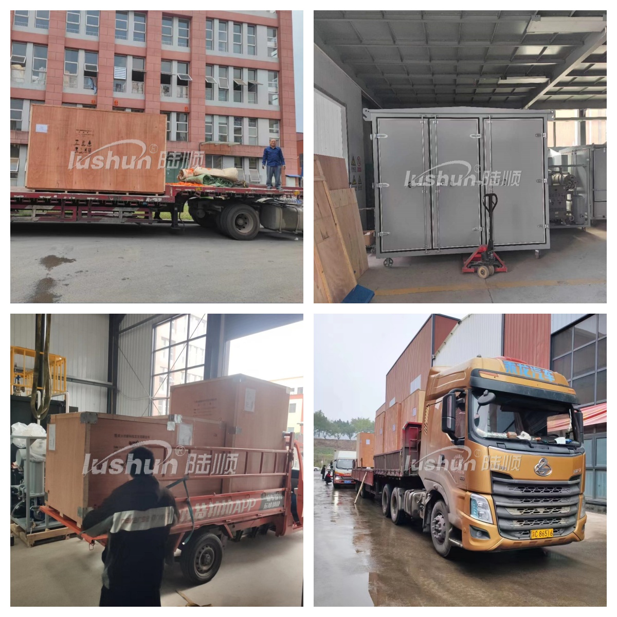
The pipeline flushing equipment (flushing pump flushing equipment) is designed to filter out contaminants generated during pipeline construction (installation), improve system cleanliness, and maintain oil cleanliness within the contamination tolerance of key hydraulic components in the system. This ensures the reliability of the hydraulic system and the service life of components, serving as a necessary measure to eliminate or minimize early equipment failures.
The pipeline flushing equipment is specially developed by our company for pipeline flushing and load testing of hydraulic systems in the shipbuilding and metallurgy industries. It features an attractive appearance, compact structure, easy operation, reliable performance, and low noise. It is particularly suitable for offline flushing and test operations of hydraulic system pipelines in large ships and metallurgical equipment. The equipment is compatible with various media such as hydraulic oil, lubricating oil, and diesel oil. As this device is mainly used for chemical flushing, the selected flushing pump is different from that used for lubrication flushing.
Composition of the Device
The device consists of a high-flow pump (centrifugal pump), oil tank, filtration system, heater, instruments, electrical control cabinet, sampling valve, and other components.
Working Principle
During operation, temporary pipelines connect the inlet and outlet of the device to the system tank and the inlet header of the pipeline system to be flushed respectively, forming a temporary circulation system. The high-flow pump suctions chemical oil from the bottom of the oil tank, which then flows through the pipeline check valve, pressure relief regulating valve, the system to be flushed, coarse filter, and fine filter, and finally returns to the tank. The flushing chemical circulates in the pipeline under a certain pressure and flow rate, and the liquid flow impacts the dirt attached to the inner wall of the pipeline to make it fall off. The dirt is then filtered out by the coarse and fine filters, ensuring that the chemical liquid entering the pipeline system meets the operating standards for cleanliness.
Technical Parameters
Item | Unit | GCC-600H | GCC-800H | GCC-1000H | GCC-1600H | GCC-2000H | GCC-2400H | GCC-3600H | GCC-4000H |
Max.Flushing Rate | L/min | 600 | 800 | 1000 | 1600 | 2000 | 2400 | 3600 | 4000 |
Flushing Pressure | MPa | ≤1 (can be customized.) | |||||||
Filtering Stages | - | 3 stages | |||||||
Filtration Precision | - | Level 6~8(NAS1638) | |||||||
Total Power | -KW | 35 | 42 | 50 | 65 | 75 | 95 | 135 | 141 |
Power Supply | -V | 380V/50Hz(can be customized.) | |||||||
Net Weigh | kg | 2600 | 2800 | 3000 | 3600 | 3700 | 3800 | 4500 | 5000 |